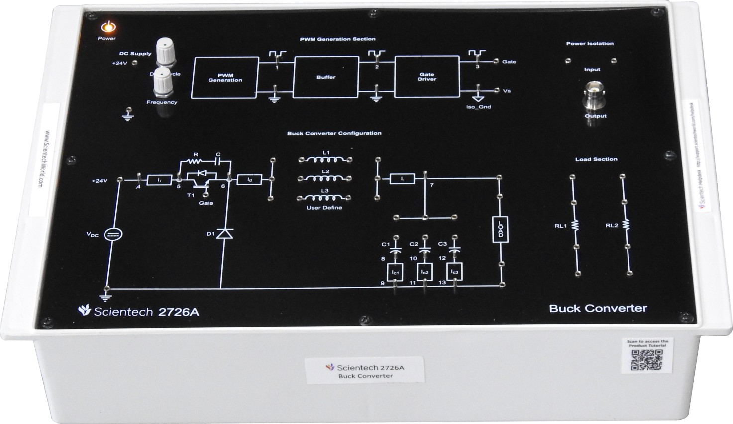
Scientech 2726A Buck Converter is a compact and user-friendly learning platform which is very useful for students to understand the concept of PWM generation technique, and Buck Converter topology on various load configurations. It is also helpful for understanding the converter output on various filter configurations. The platform explains PWM generation technique, Buck converter operation, and power isolation circuit to measure the isolated output. The platform can also help students understand the working principles of a DC buck converter, including the basic buck converter circuit and its operation under different load conditions. It provides a practical way to study buck converter waveforms and observe the behavior of the converter at different sections.
Product Features
- Optically isolated PWM generation with Gate driver
- Inbuilt isolation section for measurement of the signal
- Space provided for external inductor connection
- Test Points provided at output of each section to measure the signals
The buck converter circuit helps students understand the fundamental topology of a buck converter, while the platform can be used to study buck converter waveforms generated during operation. It also provides a practical learning environment for exploring DC buck converter applications and understanding related DC-DC converter topologies
Buck Converter Circuit and Components
A buck converter circuit is a DC-DC power conversion circuit designed to step down a higher input voltage to a lower output voltage. It uses switching and PWM techniques to control the amount of energy delivered to the load.
The main components of a buck converter circuit typically include a switching device, diode, inductor, capacitor, and load. The switching device controls the flow of electrical energy, while the inductor and capacitor help regulate and smooth the output voltage. By adjusting the PWM duty cycle, the output voltage of a DC buck converter can be controlled according to the required load conditions.
Studying these components and their operation helps students understand buck converter waveforms, switching behavior, PWM generation, and the relationship between input and output voltage. The Scientech 2726A provides test points and an isolation section for observing and measuring signals at different stages of the converter.
Why Choose Scientech 2726A for Buck Converter Learning?
Scientech 2726A provides a practical learning platform for understanding buck converter concepts, PWM generation, and DC-DC power conversion. It helps students move beyond theoretical learning by providing hands-on experience with buck converter operation, DC buck converter configurations, and power conversion principles.
The platform is designed to help students understand buck converter circuit operation, PWM generation, power isolation, and output behavior with different load and filter configurations. Students can also study buck converter waveforms and observe how signals change at different sections of the buck converter circuit.
Key Reasons to Choose Scientech 2726A
- Practical buck converter learning: Helps students understand buck converter operation through hands-on experimentation.
- PWM generation: Supports practical learning of PWM generation techniques used to control a DC buck converter.
- Buck converter circuit analysis: Helps students understand the working and signal flow of a buck converter circuit.
- Buck converter waveform observation: Test points allow students to measure and analyze buck converter waveforms at different stages.
- Signal measurement: Inbuilt isolation and test points make it easier to measure signals within the buck converter circuit.
- External inductor connection: Space is provided for connecting an external inductor for practical buck converter experiments.
- Multiple configurations: Enables students to study a DC buck converter with various load and filter configurations.
- Power isolation: Includes an isolation section for measuring the isolated output while studying buck converter operation.
- User-friendly learning platform: Provides a compact setup for engineering students learning buck converter, DC-DC converter, and power electronics concepts.
Scientech 2726A can also help students build a foundation for understanding related converter topologies, including the buck boost converter, by developing practical knowledge of switching, PWM control, voltage conversion, and converter waveforms.
FAQs
1. What is a buck converter?
A buck converter is a DC-DC converter used to reduce a higher input voltage to a lower output voltage. It uses switching and PWM techniques to control the output voltage efficiently. A buck converter circuit typically includes a switching device, diode, inductor, capacitor, and load.
2. How to use a buck converter?
A buck converter can be used by connecting the input DC supply and load according to the circuit configuration, along with any required external components. With a learning platform such as Scientech 2726A, students can study PWM generation, connect an external inductor, explore different load and filter configurations, and use the provided test points to measure signals and observe buck converter waveforms.
3. What does a buck converter do?
A buck converter steps down DC voltage from a higher input level to a lower output level. It regulates the output by controlling the switching operation, typically through PWM. A DC buck converter is commonly studied in power electronics to understand voltage conversion, switching behavior, and output filtering.
4. How does a buck converter work?
A buck converter works by rapidly switching the input voltage on and off and controlling the switching duty cycle using PWM. The inductor stores and releases energy while the capacitor helps smooth the output voltage. By adjusting the duty cycle, the buck converter can regulate the desired lower DC output voltage.
5. What is the difference between a DC-DC converter and a buck converter?
A DC-DC converter is a broad category of circuits that convert one DC voltage level to another. A buck converter is one specific type of DC-DC converter that is designed primarily to step down voltage. Other DC-DC converter topologies include boost converters and buck boost converters, which can provide different voltage conversion functions.