

TL;DR
- This blog has been created for electronics beginners, embedded-systems developers, engineers, and anyone who wants to understand what a logic analyzer is without going through the jargon used by manufacturers.
- A logic analyzer is a test device that captures and displays numerous digital signals simultaneously, allowing you to see logic 1s and 0s and how multiple signals change and synchronise over time.
- It addresses a problem that many oscilloscopes can’t easily handle: viewing 8, 16, or even 100+ digital lines at a time to identify timing issues and decode communication protocols such as I2C, SPI, and UART.
- Logic analyzers are commonly available in three broad types: portable, modular, and PC-based, with each suited to different environments, from basic electronics setups to professional test benches.
- The concepts of probing, triggering, and timing diagrams are useful when working with embedded systems, microcontroller projects, and digital communication debugging.
Consider a common embedded systems problem. An Arduino is reading data from a temperature sensor over I2C. The code compiles, the sensor has power, and the wiring appears correct, yet the readings are incorrect or unreadable. At this point, checking the code again and again may not reveal the real problem because the fault could be in the signals moving between the two devices.
A logic analyzer lets you see what is actually happening on those communication lines. It captures the digital signals exchanged between chips and shows their transitions over time, allowing you to inspect the communication bit by bit instead of troubleshooting based only on assumptions.
This guide explains what a logic analyzer does, how it differs from an oscilloscope, the different types available, and how to use one step by step to examine a real digital signal.
Also read,
- What Is Water Resource Management and Why Is It Important?
- How Do You Choose the Right DC Electronic Load?
- How to Use a DC Power Supply Machine for Mobile Repairing: Complete Beginner’s Guide
What Is a Logic Analyzer?
Digital circuits rarely fail in an obvious way. A microcontroller may send the wrong command to a sensor, a memory chip may respond at the wrong time, or a communication bus may produce a sequence of bits that looks correct at first glance but fails at a critical moment. The challenge is often not seeing whether a signal exists, but understanding what several digital signals are doing together and exactly when they change.
This is where a logic analyzer becomes useful.
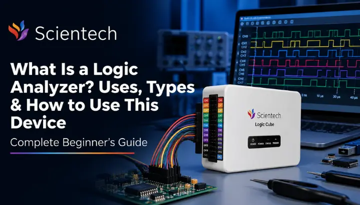
A logic analyzer is an electronic test instrument that captures multiple digital signals simultaneously and displays their logic states against time. It shows when each signal changes between high, or logic 1, and low, or logic 0, allowing you to examine the timing and relationship between signals.
For example, when a microcontroller communicates with a sensor over I2C, looking at the SDA line alone may not tell you much. You also need to see the SCL clock signal and understand how the two signals interact. A logic analyzer captures both signals together, making it easier to identify incorrect timing, missing bits, unexpected transitions, or communication errors.
Modern logic analyzers can do more than display digital waveforms. Many models can decode common communication protocols such as I2C, SPI, and UART, converting streams of 1s and 0s into readable information. This can save considerable debugging time because you can inspect the actual data being transmitted instead of manually interpreting every transition.
The basic principle has remained consistent since logic analyzers first became commercially available. Hewlett-Packard introduced the HP 5000A in 1973, one of the early commercial logic analyzers. Today’s USB-based instruments can monitor numerous channels, record large amounts of digital activity, and provide software-based protocol decoding on a computer.
In simple terms, a logic analyzer helps answer three practical questions during digital debugging: What changed, when did it change, and how did the signals interact?
Logic Analyzer vs Oscilloscope What’s the Real Difference?
If you have used an oscilloscope, you already understand half of what a logic analyzer does. But confusing two is one of most common mistakes engineering students make early on, so it’s worth being precise.
An oscilloscope measures the actual voltage of a signal continuously, over time. If a wire is meant to sit at 5V but is drooping to 3.8V due to a loading issue, oscilloscope shows you that sag directly on its display. It cares about the analog shape of the signal, its rise time, fall time, noise, ringing, and exact voltage levels, usually across two to four channels.
A logic analyzer does not care about exact voltage. It only asks one question per wire: is this signal above or below a threshold, meaning is it a logical 1 or a logical 0, at this instant? It samples each signal and interprets it as a logic high or low based on a voltage threshold, then displays those logic states over time and shows how signals on different channels relate to each other.In exchange for giving up that voltage detail, it can watch far more channels at once, commonly 8, 16, 32, or more, compared to an oscilloscope’s typical 2 to 4.
Think of it this way. Think of an oscilloscope as a tool that shows the exact voltage waveform over time, while a logic analyzer focuses on whether each sampled signal is at a logic high or low and when those states change. Different jobs, different tools.
| Feature | Oscilloscope | Logic Analyzer |
| Signal type | Analog and digital | Digital only |
| Typical channel count | 2 to 4 | 8 to 100+ |
| What it measures | Exact voltage over time | Logic high/low over time |
| Best for | Signal integrity, rise/fall time, noise, analog debugging | Timing relationships, bus/protocol decoding, multi signal digital debugging |
| Protocol decoding (I2C, SPI, UART) | Limited, on higher end models | Standard feature on most models |
| Probe complexity | Higher (measures precise voltage) | Simpler (just needs high/low detection) |
This concept can also be relevant to GATE and SSC JE questions involving digital instrumentation and measurement. A question might ask which instrument is better suited for observing timing relationships across multiple digital lines in a microprocessor bus. The answer is logic analyzer, precisely because of its high channel count and its focus on logic states rather than analog voltage detail. Many modern instruments blur this line by combining both functions into a mixed signal oscilloscope (MSO), but the underlying distinction between digital timing analysis and analog voltage measurement still holds.
What Is a Logic Analyzer Used For?
Understanding logic analyzer uses is easier once you see them grouped by the kind of problem they solve.
Debugging Embedded Systems and Microcontroller Projects
This is the most common scenario a student runs into. You’ve written firmware for an 8051, AVR, PIC, or ARM Cortex M based board, and a peripheral, an I2C sensor, an SPI flash chip, an SD card, isn’t responding as expected. A logic analyzer connected to the relevant pins can show the captured data, help you verify addresses, and let you examine whether the observed timing matches the device’s specifications.
Decoding Communication Protocols
Modern logic analyzers include built-in protocol decoders for I2C, SPI, UART, CAN, and 1 Wire, among others. Instead of manually counting bits on a timing diagram, software automatically groups raw signals into readable bytes, addresses, and data values. For a student working on an IoT or embedded project, this feature alone turns a logic analyzer from a curiosity into a genuinely useful debugging tool.
Verifying Timing Relationships and Bus Behavior
In systems where a microprocessor reads and writes to memory or peripherals over an address/data bus, correct operation depends on precise timing, setup times, hold times, and clock edges arriving in the right sequence. A logic analyzer captures multiple relevant lines together, making it easier to verify whether a device is asserting a chip-select signal at the correct moment relative to the clock.
Detecting Glitches and Intermittent Faults
Some faults only show up occasionally, a signal that glitches once every few thousand cycles, or a race condition that only appears under specific timing. Logic analyzers can be configured to trigger on a rare, specific pattern and capture a long window of data around it, which is exactly how you catch a bug that would otherwise take hours of manual observation.
Correlating Hardware Signals with Software Execution
Some advanced debugging and trace systems can correlate hardware activity with program execution or source-code information, although this goes beyond the basic capabilities of a typical logic analyzer. This is valuable during hardware software integration testing, where you need to confirm that a specific instruction actually produced expected signal on a pin.
Types of Logic Analyzer
Logic analyzers come in three broad types, and one you encounter will depend heavily on whether you’re in a college lab, a corporate R&D bench, or debugging a personal project at home.
Portable (Standalone) Logic Analyzers
These are self contained units with their own screen, controls, and processing built in, similar in form factor to a benchtop oscilloscope. They don’t need a separate computer to operate, which makes them useful in labs, field testing, or anywhere a full PC setup would be inconvenient. Standalone units can support high-speed signal capture, but their performance depends mainly on the analyzer’s sampling rate, input circuitry, memory depth, and architecture rather than simply whether they use USB or Ethernet.
Modular Logic Analyzers
These are built around a chassis or mainframe with individual plug in modules, each module adding a fixed number of channels. Need to monitor 200 channels for a large digital system? Slot in enough modules to cover it. Modular systems are the most expensive and highest performing option, commonly found in research labs, PSU testing facilities, and semiconductor verification setups, since they can be scaled up as requirements grow.
PC Based Logic Analyzers
These connect to a laptop or desktop through USB and rely entirely on the host computer’s screen and processing power to display and analyze data. This is the type most engineering students actually use, since it’s compact, affordable, and works well for classroom projects, hobbyist embedded work, and lab exercises. A low cost USB logic analyzer paired with free software is often very first hands on exposure students get to real digital signal debugging. Scientech’s PC-based logic analyzer range, including the LA 4000 and LA 5000 series, provides examples of how PC-based logic analyzers can be used for digital signal capture and analysis. These instruments show how this form factor can serve applications ranging from student projects to laboratory testing.
| Type | Portability | Typical Channel Count | Cost | Best Suited For |
| Portable/Standalone | Moderate (self contained) | Moderate to high | High | Field debugging, lab benches without a dedicated PC |
| Modular | Low (requires mainframe) | Very high (100s) | Very high | Large scale, high channel count professional systems |
| PC based | High (fits in a bag) | Low to moderate | Low to moderate | Student labs, embedded hobbyist projects, classroom use |
How to Use a Logic Analyzer A Step by Step Walkthrough
Let’s put this into practice using a realistic scenario: capturing an I2C conversation between a microcontroller and a sensor to check why data isn’t coming through correctly.
Step 1: Identify Signal Lines You Need to Probe
I2C uses two communication signal lines: SDA (data) and SCL (clock). The circuit also requires a common ground and appropriate power connections. Before touching the logic analyzer, identify these pins on your circuit, usually SDA and SCL breakout pins on your microcontroller board or sensor’s datasheet.
Step 2: Connect Probes
Attach one probe clip to SDA and another to SCL. Connect a ground clip from logic analyzer to circuit’s ground rail; a missing or poor ground connection is one of most common reasons for a garbled or noisy capture. Most classroom logic analyzers use simple wire and clip probes, since they only need to sense whether a line is high or low, not measure precise voltage like an oscilloscope probe would.
Step 3: Set Voltage Threshold
Configure the analyzer’s input threshold or logic standard according to the signal levels being measured. Different signal standards can use different logic thresholds, so the analyzer’s input threshold should be appropriate for the signals being measured.
Step 4: Configure Trigger
A trigger tells the logic analyzer exactly when to start recording. For I2C, a common choice is to trigger on the falling edge of SDA while SCL is high, which marks I2C “start condition.” Without a trigger, you’d have to manually scroll through a long, mostly idle capture hoping to spot the exact moment your data transfer happened.
Step 5: Capture and Decode
Run capture while your circuit performs transactions you want to inspect, for example, calling code that reads sensors. Once captured, use software’s built in I2C decoder to convert raw high/low pulses into readable addresses and data bytes. At this point, you can directly check whether the microcontroller is sending the sensor’s correct I2C address, whether the sensor is sending an acknowledgment bit, and whether returned data bytes match what the datasheet specifies.
Step 6: Interpret Results
If the decoded I2C address doesn’t match the address specified by the sensor’s datasheet, check the device’s address-selection pins and the address configured in your code. If there’s no acknowledgement, check the sensor’s power, wiring, I2C address, pull-up resistors, and bus configuration. The device may also be held in reset or may not support the communication settings being used. These are common issues when building a first I2C circuit. If data bytes look garbled but address and acknowledgment are correct, check your clock speed against what sensor supports.
This same process, identify signals, connect probes, set threshold, trigger, capture, decode, applies whether you’re debugging I2C, SPI, UART, or a parallel memory bus. Only trigger condition and decoder you select change.
Common Mistakes Students Make With Logic Analyzers
A few errors show up repeatedly when students use a logic analyzer for the first time. Forgetting to connect ground probes is the most frequent one, and it often produces a capture full of random, meaningless toggling that looks like a hardware fault but is really just a missing reference. Setting the wrong voltage threshold is another common issue, since a 3.3V signal read against a 5V threshold can appear permanently low even though the circuit is working correctly.
Students also sometimes expect logic analyzers to tell them why a circuit is failing. It won’t. It only shows you what happened on wires; interpreting that against protocol specification or datasheet is still your job. Finally, skipping trigger setup and trying to manually scroll through a massive raw capture wastes far more time than configuring even a basic trigger condition upfront.
Conclusion
If you’re studying digital electronics, embedded systems, or working on microcontroller-based projects, learning to use a logic analyzer can be highly useful. A logic analyzer solves a specific, common problem: seeing what’s actually happening across multiple digital signals when something in your circuit isn’t behaving as expected. It doesn’t replace an oscilloscope, it complements it, and knowing when to reach for which instrument is itself a mark of a competent engineer.
Start with a low-cost, PC-based logic analyzer for your own projects. Practice the trigger, capture, and decode workflow on something simple, such as an I2C sensor, and the concept will become much easier to understand than by reading about it alone.
Frequently Asked Questions
A logic analyzer is used to capture and display multiple digital signals from a circuit at same time, so engineers can see exact timing and sequence of 1s and 0s. It’s most commonly used to debug embedded systems, verify communication protocols like I2C and SPI, and catch timing related faults that are hard to spot any other way.
An oscilloscope measures exact analog voltage of a signal over time, while a logic analyzer only checks whether a signal is above or below a threshold, showing it as a logical high or low. This lets a logic analyzer monitor far more channels at once, but it gives up the ability to see fine voltage detail that an oscilloscope provides.
Entry level, PC based logic analyzers commonly offer 8 to 16 channels, which is enough for most student projects and single communication buses. Professional modular systems can scale to 100 or more channels for complex digital systems with many simultaneous signals.
Many modern logic analyzers, including some affordable PC-based models, offer built-in or software-based decoders for I2C, SPI, UART, and other common protocols. This converts raw captured highs and lows directly into readable addresses and data bytes without manual bit counting.
Logic analyzers can be relevant when studying digital measurement and instrumentation concepts for engineering exams, particularly when comparing digital measurement instruments and sampling concepts. It can be relevant to questions covering digital instrumentation, measurement, timing, and digital communication concepts, depending on the exam syllabus and question pattern.
“Digital logic analyzer” and “logic analyzer” refer to the same instrument. The word “digital” simply emphasizes that the device works exclusively with digital (high/low) signals, as opposed to an oscilloscope, which also handles analog signals.