

TL;DR
- This blog is for communication engineering students, electronics engineers and everyone interested about Frequency Division Multiplexing (FDM), its working, types, advantages, and applications.
- FDM divides the available frequency spectrum into separate bands, assigning one frequency band to each signal so multiple signals can travel through the same medium simultaneously.
- Small guard bands are used to separate neighboring frequencies and the combined FDM signal can be better understood by looking at it as a spectrum.
- The blog explains conventional FDM and compares it with related techniques such as WDM, OFDM, and FDMA, and compares FDM with TDM and WDM based on bandwidth, timing, and applications.
- FDM is used in AM/FM radio, cable TV, legacy telephone systems, and related optical communication technologies, with a numerical example showing how to calculate the total bandwidth required.
Also Read,
- What Is Water Resource Management and Why Is It Important
- How Do You Choose the Right DC Electronic Load ?
- How to Use a DC Power Supply Machine for Mobile Repairing
When multiple signals need to travel through the same communication channel, sending each one separately can require a large amount of bandwidth and infrastructure. Frequency Division Multiplexing (FDM) solves this problem by dividing the available frequency spectrum into separate bands and assigning each signal its own frequency range. This allows multiple signals to be transmitted over the same medium at the same time without having to take turns.
FDM has been used for decades in communication systems such as radio broadcasting, cable television, and analog telephone networks. Its basic idea also helps explain related techniques such as Wavelength Division Multiplexing (WDM), Orthogonal Frequency Division Multiplexing (OFDM), and Frequency Division Multiple Access (FDMA).
In this guide, you will learn how FDM works, how its frequency bands and guard bands are arranged, how to calculate the bandwidth required for an FDM system, and where the technique is used. We will also compare FDM with TDM and WDM to make the differences between these multiplexing techniques easier to understand.
What Is Frequency Division Multiplexing?
Frequency division multiplexing (FDM) is a technique that splits available frequency spectrum of a communication channel into multiple non overlapping frequency bands and assigns one band to each individual signal. Every signal transmits continuously, at the same time as all others, because each one occupies its own private frequency slot rather than competing for shared time or space.
FM radio broadcasting is a familiar example of frequency-based channel allocation. Multiple stations can broadcast simultaneously, with each station assigned its own frequency band within the available spectrum. What separates 91.1 MHz from 93.5 MHz is not timing but frequency: each station occupies a fixed, unique slice of spectrum, and a receiver isolates one station by tuning to that slice while rejecting rest. Cable television and legacy analog telephone systems use identical principles to carry many channels or calls over a single physical medium.
This is distinct from methods where multiple signals take turns on a shared channel. In FDM, several signals ride the same physical medium simultaneously, separated only by the frequency band each one occupies.
How Does Frequency Division Multiplexing Work?
FDM works in three stages: modulation, combining, and separation at the receiving end.
Step 1: Modulate each signal onto a different carrier
In a conventional FDM system, each input signal has its own original frequency range, often a baseband signal, which is then shifted to an assigned frequency band. On their own, multiple baseband signals would occupy overlapping frequency ranges, so they need to be shifted to different frequency bands before they can be combined using conventional FDM. Each signal is modulated onto its assigned carrier frequency using an appropriate modulation technique, such as AM, FM, or another modulation scheme depending on the system. This shifts the signal up to a completely different position in frequency spectrum, one that does not overlap with any other signal’s assigned position.
Step 2: Add guard bands and combine everything into one composite signal
Even with careful frequency assignment, real filters are not perfect, and a signal’s edges can spill slightly beyond its intended range. To stop one signal’s spillover from corrupting its neighbor, engineers insert a small strip of unused frequency called a guard band between adjacent channels. Once every signal has been shifted to its own frequency slot with guard bands in place, all shifted signals are added together electronically to form one composite signal.
Step 3: Transmit, then separate at receiver
This single composite signal now travels down shared medium, whether that is a coaxial cable, a twisted pair, free space (radio waves), or an optical fiber. At the receiving end, a set of bandpass filters, one for each original signal, picks apart a composite signal. Each filter is tuned to let only its assigned frequency band pass through and blocks everything else. After filtering, each recovered signal is demodulated back down to its original baseband form. This entire recovery process is called demultiplexing, and the device that performs it is called a demultiplexer, or demux.
Multiplexer (mux) combines on the transmitting side, and demultiplexer (demux) separates on the receiving side. In a two way FDM link, both ends need a mux/demux pair so signals can flow in both directions.
What Does an FDM Signal Look Like in the Frequency Domain?
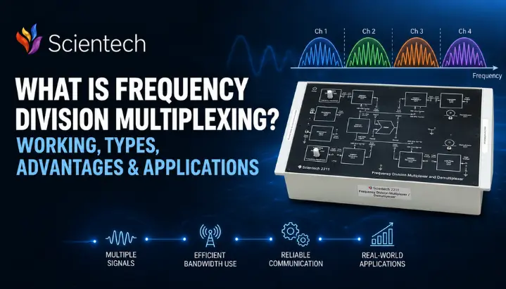
If you plotted the frequency spectrum of an FDM composite signal on a graph, with frequency on horizontal axis and amplitude or power on vertical axis, you would see a series of separate humps, each one representing one modulated signal, with narrow gaps (guard bands) between consecutive humps. This is very different from what the same signals look like in the time domain, where they overlap and appear to blend into one messy waveform.
An FDM signal is often easier to visualize in the frequency domain, where its individual channel bands and guard bands can be seen clearly. In the time domain, all FDM channels are present on the shared medium simultaneously, so an oscilloscope typically shows a single composite waveform rather than clearly separating the individual channels. To actually see individual channels, you need a spectrum analyzer, which shows amplitude versus frequency rather than amplitude versus time. On a spectrum analyzer display, each channel appears as its own labeled hump sitting at its assigned carrier frequency, exactly the picture used in most FDM textbook diagrams.
In traditional telephone FDM systems, a voice channel was commonly allocated a 4 kHz channel bandwidth, while the nominal voice-frequency range was approximately 300 Hz to 3400 Hz. Twelve such channels combine to form a “group” occupying 48 kHz, and multiple groups combine into larger “supergroups,” a hierarchy that was the backbone of analog long distance telephone networks for decades.
FDM Numerical Example
A question like this is common in communication-systems exams, so working through it helps build the calculation skills tested in such questions.
Problem: Five voice signals, each requiring a channel bandwidth of 4 kHz, need to be frequency division multiplexed onto a single channel. If a guard band of 500 Hz is required between every pair of adjacent channels, what is the minimum total bandwidth required for the multiplexed signal?
Step 1: Bandwidth used by signals themselves
Each signal needs 4 kHz. Total for 5 signals = 5 × 4 kHz = 20 kHz
Step 2: Bandwidth used by guard bands
Guard bands sit between adjacent channels only, not before first or after last. For 5 channels, number of gaps between them = 5 − 1 = 4 Total guard band space = 4 × 500 Hz = 4 × 0.5 kHz = 2 kHz
Step 3: Add both together
Minimum total bandwidth = 20 kHz + 2 kHz = 22 kHz
Answer: multiplexed FDM signal requires a minimum bandwidth of 22 kHz.
Exam variations of this question often change the number of channels, per channel bandwidth, or ask you to work backward (given a total available bandwidth, find maximum number of channels that fit). The method stays identical: multiply the number of channels by the bandwidth required per channel, then add the guard-band space for the gaps between adjacent channels, not for the total number of channels.
Types of Frequency Division Multiplexing
FDM is not a single rigid technique. It shows up in a few closely related forms depending on application and how frequency bands are structured.
Baseband FDM
This is the classic form described above, where multiple signals are individually shifted to separate frequency bands and combined into a composite signal. Traditional analog telephone trunk systems and legacy cable television distribution used this approach directly.
Wavelength Division Multiplexing (WDM)
WDM uses a closely related multiplexing principle in optical fiber by assigning different data channels to different wavelengths of light. Different data streams are carried on different colors (wavelengths) of laser light, all traveling down the same fiber strand simultaneously. Dense WDM (DWDM) systems used in real telecom backbones can combine 40, 80, or even more wavelength channels onto a single fiber, and this is one of main reasons modern internet infrastructure can move such enormous amounts of data. Optical fiber communication training systems can also be used to demonstrate how multiple optical channels share a fiber.
Orthogonal Frequency Division Multiplexing (OFDM)
OFDM divides a channel into many closely spaced orthogonal subcarriers. Their spectra can overlap, but the subcarriers are mathematically arranged so that they can be separated at the receiver with minimal inter-carrier interference under ideal synchronization conditions. This greatly reduces the need for guard-band spacing between subcarriers and allows OFDM to use spectrum more efficiently than conventional FDM. OFDM is used in technologies such as Wi-Fi, 4G LTE, and several digital television broadcasting standards, and understanding basic FDM is a natural stepping stone before studying OFDM in a communication systems course.
Frequency Division Multiple Access (FDMA)
FDMA is a multiple-access technique in which different users are assigned separate frequency channels so they can access a shared communication system simultaneously. FDMA applies frequency-based channel separation to multiple access: different users are assigned separate frequency channels so they can access the same communication system simultaneously. FDM, by contrast, is the broader multiplexing concept of combining multiple signals into one shared medium by assigning them different frequency bands.
Frequency Multiplexer: Hardware Behind FDM
Frequency multiplexer is a physical (or digital signal processing) device that performs actual combining steps in an FDM system. In a conventional analog FDM system, the transmitter typically uses modulation, filtering, and combining stages for each input channel that adds all individually filtered signals into one composite output.
On the receiving side, the corresponding demultiplexer reverses this exact process using bandpass filters tuned to each channel’s frequency, followed by demodulators that convert each recovered band back to baseband. In older analog telephone exchanges, these were literal physical circuit cards, one modulator/filter pair per voice channel, mounted in a rack. In modern systems, the same functions are often implemented as software running on digital signal processors, but underlying signal flow has not changed.
For an engineering learner, the practical takeaway is this: in a conventional analog FDM block diagram, the multiplexer can be understood as the combination of modulation, filtering, and signal-combining stages.
Advantages of Frequency Division Multiplexing
FDM has stayed relevant for close to a century of communication engineering because of a specific set of strengths.
FDM does not require the precise time-slot synchronization used by TDM because channels are separated in frequency rather than time, not by when it transmits. This avoids the precise timing synchronization required by TDM, which can simplify the handling of continuously transmitted analog channels. Every channel transmits continuously rather than in short bursts, which suits signals like voice and analog video that do not tolerate being chopped into time slices well. FDM also handles a mix of analog signal types naturally, since modulation techniques like AM and FM were originally designed for exactly this kind of analog signal transport. Finally, because each channel occupies its own frequency band, interference or frequency-selective fading concentrated in one part of the spectrum may affect one or more channels more strongly than others.
Disadvantages of Frequency Division Multiplexing
The same design that makes FDM simple also introduces real costs, and these limitations are exactly why later techniques like TDM and OFDM were developed.
In conventional FDM, guard bands consume spectrum without carrying useful data, reducing the amount of bandwidth available for the individual channels, so a meaningful fraction of total bandwidth is wasted purely on keeping channels from interfering with each other. Conventional analog FDM systems require separate signal-processing paths for the individual channels, which can increase hardware cost and complexity as the number of channels grows. IIn a conventional fixed-channel FDM system, a frequency band remains allocated to its channel even when little or no information is being transmitted. Traditional FDM systems were commonly implemented for analog signals, although frequency-division techniques are also used with digital signals, including OFDM-based systems. And a strong interfering signal or intermodulation distortion in an FDM system can create unwanted frequency products that land inside a neighboring channel’s band, a problem that gets worse as more channels are packed closer together.
FDM vs TDM vs WDM: Quick Comparison
| Parameter | FDM | TDM | WDM |
| What is divided | Frequency spectrum | Time slots | Optical wavelength (light color) |
| Signal domain | Primarily analog | Primarily digital | Optical |
| Timing synchronization | Not required | Required (precise clocking) | Not required |
| Guard mechanism | Guard bands (frequency) | Guard time (small time gaps) | Guard bands (wavelength spacing) |
| Bandwidth efficiency | Lower (guard band overhead) | Higher for bursty digital data | Very high (many wavelengths per fiber) |
| Typical medium | Copper wire, radio spectrum | Digital telephone/data links | Optical fiber |
| Common applications | FM/AM radio, cable TV, legacy telephony | Digital telephone exchanges, T1/E1 lines | Long haul internet backbones, DWDM |
Applications of Frequency Division Multiplexing
FDM is not a museum piece technology. It is still directly responsible for services engineering students use daily.
Radio and television broadcasting is the most visible example. Every FM and AM station in a city broadcasts continuously and simultaneously, each on its own assigned frequency, which is exactly why you can switch stations instantly by turning a dial or pressing a button rather than waiting for a scheduled slot.
Cable television distribution carries dozens of TV channels down a single coaxial cable into a home, with each channel occupying its own frequency band inside the cable’s total bandwidth, the same principle scaled up.
Legacy analog telephone trunk systems used FDM extensively to combine many voice calls onto a single long distance line, using group/supergroup hierarchy mentioned earlier. Most of this infrastructure has since moved to digital TDM and packet based systems, but FDM’s telephone heritage is why the technique appears so heavily in classic communication systems textbooks.
First generation (1G) mobile networks relied on FDMA to give each active phone call its own frequency channel within cellular spectrum, before 2G and later standards moved toward TDMA and CDMA based access schemes.
DWDM is widely used in high-capacity optical transport and backbone networks, where multiple wavelength channels share the same fiber.
Which Multiplexing Technique Should You Study Next?
FDM is the conceptual foundation for a cluster of related techniques that build directly on it. Once frequency based channel separation makes sense, TDM (time based separation), OFDM (overlapping orthogonal sub carriers), and WDM (optical wavelength separation) all become much easier to learn, because each one modifies exactly one part of FDM idea rather than introducing something entirely new. .